Aquaponics plumbing is the circulatory system of your entire setup. Get pipe diameter, pump placement, and flow routing right, and fish stay healthy, plants receive consistent nutrients, and your maintenance workload shrinks. This guide covers every core decision — from system type selection to final leak check — so your water always moves exactly where it should.
Aquaponics Plumbing in 2026: Key Principles at a Glance
- Velocity target: Keep flow in main supply lines between 1 and 3 ft/s (0.3–0.9 m/s) — fast enough to carry solids forward, slow enough to avoid pipe erosion and disruptive turbulence.
- System type defines layout: Flood & drain, deep water culture, and continuous flow each demand different pipe diameters, slopes, and flow patterns; get this choice right before cutting any pipe.
- Material certification matters: Schedule 40 PVC meeting NSF/ANSI 61 is the accepted standard for food-contact aquaponics plumbing — uncertified materials introduce unnecessary risk to fish and edible produce alike.
- Redundancy saves fish: A backup pump or parallel bypass line costs a fraction of a complete fish loss; every well-designed water circulation network builds this in from day one.
What Makes Aquaponics Plumbing the Foundation of Every Healthy System?
Think of your water circulation network the way a cardiologist thinks about the vascular system. When flow is consistent and unrestricted, nutrients reach every part of the system, waste gets cleared efficiently, and the whole organism stays in balance. Remove that circulation — even briefly — and decline begins fast.
In an aquaponics setup, water carries dissolved fish waste, dissolved oxygen, nitrifying bacteria, and plant nutrients through a closed loop connecting fish tanks, grow beds, and a sump. If any section of that loop moves too slowly, heavier solids settle out and decompose, driving ammonia spikes that stress fish and compromise plant roots. If it moves too quickly, beneficial bacterial colonies in the grow media get disturbed before they can establish, which undermines the biological cycling that does most of the system’s real work.
Good design solves both problems before a drop of water flows. That means mapping pipe diameters, drainage slopes, access points, and backup flow paths on paper — before cutting any PVC. Systems built this way run quieter, require less daily intervention, and outlast improvised setups by several years. Understanding what an optimised piping arrangement actually looks like in practice helps translate these principles into a real build.
Heavily stocked tanks benefit from up to twice per hour.
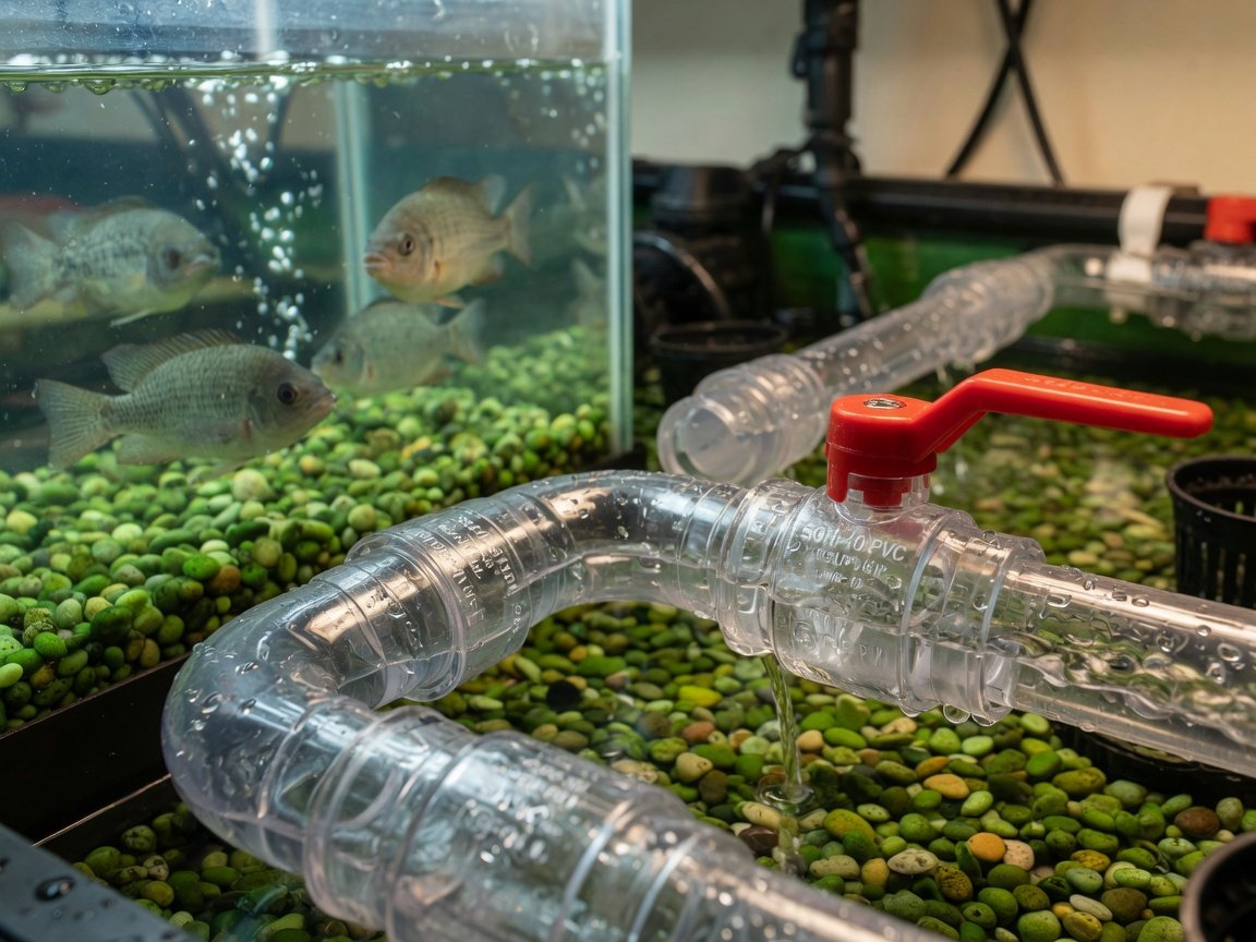
How Do Flood & Drain, DWC, and Continuous Flow Differ in Their Plumbing Requirements?
Your choice of growing method is the single biggest driver of how your piping system runs. Each approach creates different flow demands, and designing for the wrong one adds unnecessary cost and ongoing complexity.
| System Type | Typical Inlet Size | Drain Line Size | Key Plumbing Feature | Best For |
|---|---|---|---|---|
| Flood & Drain | ¾” – 1″ | 1½” – 2″ | Bell siphon or timed flood valve | Mixed crops, media beds |
| Deep Water Culture | ¾” – 1″ | 1″ – 1½” | Air stone / diffuser supply lines | Leafy greens, herbs |
| Continuous Flow (NFT) | ½” – ¾” | 1″ – 1½” | Constant-flow manifold and return | Fast-cycling crops |
Flood & drain fills the media bed to a set depth, then drains it completely before the next cycle begins. The wet-dry rhythm drives root oxygenation and supports the dense bacterial colonies that convert fish waste into plant-available nitrogen. Drain lines need to be sized at 1½” to 2″ so the bed empties fully before the next flood arrives. Undersizing the drain is the most common flood & drain mistake — it causes the bed to overflow rather than drain, saturating root zones and creating anaerobic pockets in the media.
Deep water culture maintains a constant water level with plants floating on foam rafts. Flow is gentler and more consistent than flood & drain. The main plumbing requirement is reliable aeration via air stones or diffusers — dissolved oxygen must stay above 5 mg/L for healthy root function. Leafy crops like lettuce thrive in DWC arrangements because steady nutrient delivery matches their rapid growth cycle. Plumbing complexity is lower than flood & drain, but air supply lines must be correctly sized to prevent stratification in deeper raft channels.
Continuous flow keeps water moving at a controlled rate through channels or NFT (nutrient film technique) tubes. Pumps run constantly, so reliability and backup capacity become critical design considerations. The primary plumbing challenge is maintaining the specific film depth or channel level that each crop variety needs — too deep and roots suffocate; too shallow and nutrient uptake stalls. Sump sizing must accommodate the continuous return volume without overflow.
What Tools and Materials Do You Need Before You Start Plumbing?
Gathering the right materials before work begins saves time and prevents the more serious problem of using unsuitable components that compromise food safety or fail prematurely. The aquaponics environment is wet, often warm, and biologically active — materials that wouldn’t last in a standard plumbing application won’t last here either.
Pipe: Schedule 40 PVC is the standard for main supply and drain lines across aquaponics systems of all sizes. It’s durable, affordable, easy to cut and join, and widely available. For areas under mechanical stress or higher sustained pressure, Schedule 80 provides additional wall thickness. Always confirm the material carries NSF/ANSI 61 certification before purchasing — this standard verifies that the product is safe for drinking water contact, which is the appropriate baseline for food-producing systems. If you’re working with existing pipe of uncertain origin, the guidance on whether PVC is safe for aquaponics food production sets out exactly what to look for.
Fittings: Use long-radius sweep elbows wherever the piping changes direction. Standard short-radius 90° elbows create turbulence and add significant head loss — in a system with multiple direction changes, this difference is measurable at the pump. Ball valves allow you to isolate any section for maintenance without draining the entire system. Tee fittings manage flow splits and merges at branch points. Every fitting must match your pipe’s schedule and nominal diameter — mixing Schedule 40 and Schedule 80 fittings at a single join creates a leak point.
Sealant and adhesive: Solvent cement creates a permanent chemical bond between PVC surfaces and is the correct choice for all fixed, buried, or hard-to-access connections. Threaded fittings need food-safe PTFE tape or rated thread sealant paste applied to every thread. Standard plumbing sealants not rated for food contact have no place in an aquaponics system.
- Pipe cutter or fine-tooth hacksaw
- Deburring tool or fine sandpaper (smooth every cut end before fitting)
- Tape measure and permanent marker
- Ball valves — at least one per major system branch
- Long-radius sweep elbows and tee fittings sized to your pipe diameter
- NSF/ANSI 61-certified Schedule 40 PVC pipe
- Food-safe PTFE tape and thread sealant paste
- PVC primer and solvent cement for permanent joins
- Inline flow meter (optional but strongly recommended during commissioning)
How Do You Design an Aquaponics Plumbing Layout Step by Step?
Working through the hydraulic layout methodically before any physical work begins prevents the most common and costly mistakes. Each step below builds on the previous one — skipping ahead usually means revisiting earlier decisions under time pressure.
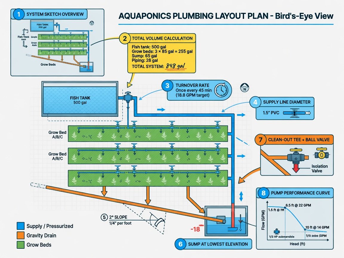
- Sketch the full system on paper. Map every component — fish tank, grow beds, sump, pump, and return lines — in rough proportion. Draw arrows showing the intended direction of water movement at every point. This single step surfaces most potential conflicts before they cost money.
- Calculate your total water volume. Add up the volume of the fish tank, grow beds (media displaces roughly 30–40% of nominal bed volume), and sump. This number drives every downstream decision about pump selection and pipe sizing.
- Set your turnover rate target. For most systems, cycling total volume once per hour provides adequate biological filtration and oxygenation. Heavily stocked tanks benefit from twice per hour. Convert this to gallons per minute (GPM) or litres per minute — this becomes your design flow rate.
- Size your main supply lines. Using your design flow rate and a target velocity of 1–3 ft/s, calculate the pipe diameter needed via Q = A × V, where Q is flow rate, A is internal pipe cross-section area, and V is velocity. Standard 1″ pipe handles most small-to-mid residential systems; step up to 1½” or 2″ for larger setups or multiple grow bed branches.
- Size drain lines one step larger than supply lines. Add a slope of at least 1/8″ per foot (1%) to all gravity-drain runs. Flat or back-sloped drain lines are the primary cause of solid accumulation and recurring blockages in flood & drain systems.
- Position the sump at the lowest point. The sump collects gravity-drained return water and feeds the pump. Placing it at the lowest point means gravity handles all drainage passively, reducing pump workload and simplifying the overall layout significantly.
- Plan access and clean-out points throughout. Fit a tee with a removable cap every 10–15 feet on long runs. Place ball valves before and after every major component so any section can be isolated without shutting down the entire system. Document every clean-out location on your schematic.
- Verify pump performance against your design head. Total head is the vertical lift from sump to the highest delivery point, plus friction losses from pipe length and fittings. Cross-check your design flow rate against the pump manufacturer’s performance curve at this head value — your required flow should fall in the pump’s efficient mid-range, not at the top of its curve where output drops sharply.
How Do You Calculate Flow Rate and Match It to Pipe Diameter?
Flow rate and pipe diameter are directly linked — change one and you change the other. The design goal is to maintain velocity in the 1–3 ft/s range across all main supply lines. Below 1 ft/s, heavier solids drop out of suspension and begin decomposing inside the pipe. Above 3 ft/s, turbulence increases, fine particles get resuspended throughout grow beds, and fittings erode faster than they should.
The core relationship is Q = A × V, where Q is flow rate (GPM or L/s), A is the pipe’s internal cross-sectional area (π × r²), and V is velocity. Rearranging for radius gives you the minimum pipe size at your target velocity and design flow rate. In practice, this consistently points toward 1″ nominal pipe for flows up to approximately 10 GPM, and 1½” to 2″ for flows between 10 and 30 GPM in residential-scale systems.
Head loss from pipe length, elevation changes, and fittings reduces the actual flow your pump delivers. The Hazen-Williams and Darcy-Weisbach equations both model this precisely for long or complex runs. For most hobby and small commercial systems, a practical shorthand works well: when accounting for fittings, add 20–30% to your measured pipe length as equivalent length, and select a pump rated at least 25% above your calculated flow demand. This buffer keeps the pump operating in the efficient portion of its performance curve as the system ages and minor deposits accumulate.
1″ Schedule 40 PVC → approximately 4–5 GPM
1½” Schedule 40 PVC → approximately 9–11 GPM
2″ Schedule 40 PVC → approximately 16–20 GPM
Exact values vary by wall thickness and fitting configuration — verify with your pump’s performance curve.
Which Fittings and Connectors Deliver the Cleanest, Most Efficient Flow?
Once pipe sizing is settled, fitting selection determines how much of that theoretical flow you actually deliver to your fish and plants. Poor choices here add head loss, create turbulence hotspots, and give solids somewhere to accumulate — three problems that reinforce each other over time.
Sweep elbows vs. standard short-radius elbows: A long-radius sweep elbow guides water around direction changes with minimal flow disruption. A standard short-radius 90° elbow creates a sharp turn that can add the equivalent of several feet of straight pipe in head loss. In a system with multiple bends — and most aquaponics layouts have several — this difference compounds into a meaningful reduction in delivered flow at your grow beds. Use sweep elbows wherever the installation allows.
Solvent weld vs. threaded vs. push-fit: Solvent-welded joins create a chemically bonded connection that’s effectively as strong as the pipe itself — the correct choice for all permanent, buried, or difficult-to-access sections of the system. Threaded fittings are removable, which is useful at service points; apply food-safe PTFE tape to every thread and inspect annually, as vibration can cause gradual loosening. Push-fit fittings assemble quickly and work well for commissioning tests or temporary connections, but confirm the specific product’s pressure rating before using one in a permanent installation.
Union fittings: Fit a union on both sides of your pump when the installation allows it. Unions let you remove the pump for servicing without disturbing any solvent-welded pipe runs. A pair of unions costs very little upfront and saves real time and frustration at every maintenance interval from that point forward.
Where Should Your Pump Go — and Why Does Redundancy Matter?
Pump placement is one of the most consequential decisions in any aquaponics layout. The pump’s location affects operating efficiency, component lifespan, and — critically — how quickly you can service it when the system needs attention.
Place the primary pump submerged in the sump or positioned below the water level of the fish tank so it operates in flooded suction at all times. Submersible pumps in this configuration never run dry, and running dry is the primary cause of motor failure in aquaponics systems. If you’re using an external inline pump, position it below the sump water line with a flooded inlet to eliminate priming problems and reduce the risk of cavitation, which erodes impellers over time.
Redundancy is a design requirement, not an optional upgrade. A second pump plumbed into a parallel bypass line provides immediate failover without manual intervention when the primary pump fails — and all pumps eventually fail. At minimum, keep a tested spare pump on the shelf and ensure your system has the isolation valves needed to swap it in within a few minutes. Flow interruptions create oxygen depletion in heavily stocked tanks within an hour or less, so the response window is narrow.
How Does Solids Management Connect to Your Plumbing Design?
Solids are the primary ongoing threat to a well-designed hydraulic layout. Fish waste, uneaten feed, and decomposing plant material accumulate wherever flow velocity drops below the carrying threshold. Left in place, they break down anaerobically, producing hydrogen sulphide and ammonia loads that stress fish and disrupt the beneficial bacterial populations your system depends on.
The most effective approach is mechanical solids removal before water reaches your grow beds. A radial flow filter is straightforward to build at home and uses centrifugal action to settle suspended solids from the fish tank outflow. Positioned immediately after the fish tank outlet and before the grow bed inlet, it keeps media clean, extends maintenance intervals, and protects root zones from the anaerobic conditions that concentrated decomposing solids create.
Plumb the filter’s bottom drain with a ball valve for easy cleanout. The collected solids are nutrient-dense — many aquaponics growers route them to a worm bed rather than discarding them, converting a maintenance byproduct into a resource. Keeping solids out of the main loop also protects the biological processes at the core of how the system functions: the nitrification cycle that converts ammonia to plant-available nitrates operates most reliably when it isn’t competing with high suspended solid loads in the water column.
How Do You Prevent Leaks and Build a Sustainable Maintenance Routine?
Leak prevention starts at installation, not at the first drip. The most reliable approach combines correct material selection, thorough joint preparation, and a commissioning process that identifies problems before they turn into failures.
When solvent-welding PVC, clean and prime both surfaces before applying cement. Primer softens the PVC and allows the cement to create a true molecular bond rather than just a surface adhesion. Push the fitting to full depth while the cement is still fluid, hold it without rotating for 30 seconds, and allow the full cure time specified by the cement manufacturer before putting the line under pressure — typically 24 hours at normal temperatures.
Commission new plumbing before introducing fish. Fill the system with plain water, run the pump for 24 hours, and inspect every joint and fitting under operating conditions. Mark any seeps immediately. Fixing a dry joint before fish are present takes minutes; fixing it with livestock in the system means either draining it or working carefully around living animals.
- Inspect all visible joints, valve stems, and union faces monthly
- Check flow meter readings weekly — an unexpected drop indicates a developing blockage or pump performance decline
- Flush and clean mechanical filter components on your regular schedule
- Replace rubber gaskets and O-rings every one to two years, or at the first sign of weeping
- Keep a small kit of spare fittings, a short pipe length, and thread sealant accessible at all times
What Does Smart Aquaponics Plumbing Look Like in 2026?
The most significant shift in aquaponics plumbing in 2026 is the adoption of low-cost inline flow sensors connected to basic automation controllers. These sensors monitor flow rate continuously at key system points and trigger alerts — or switch automatically to a backup pump — when flow drops below a set threshold. What previously required manual daily inspection now happens autonomously, reducing the risk of silent failures that go unnoticed until fish show visible stress.
Vertical system designs are also reshaping hydraulic layout thinking. As growers maximise production per square metre, gravity-fed multi-tier configurations are increasingly common — water flows downward through stacked grow levels before returning to the sump, using gravity to handle most of the head work. This reduces pump energy demand and simplifies the layout by eliminating the need to pump water to multiple separate grow bed locations at different heights. The plumbing advantages of vertical configurations extend well beyond space efficiency into tangible reductions in system complexity.
Modular plumbing systems — pre-fabricated manifold blocks that standardise connections between components — are emerging as a practical alternative to fully custom-cut PVC networks. These reduce build time, improve joint consistency, and make scaling a system up considerably simpler. For builders starting from scratch, a modular approach often results in a cleaner, more maintainable layout than custom-cut PVC assembled under build pressure.
Frequently Asked Questions About Aquaponics Plumbing Layout
What pipe size is most commonly used for aquaponics?
For most hobby and small-scale systems, 1″ Schedule 40 PVC handles main supply lines and 1½” to 2″ handles gravity drain runs. Larger multi-bed or commercial systems typically step up to 1½” supply lines and 2″ to 3″ drains. When in doubt, size up — an oversized drain line causes no operational problems, while an undersized one causes overflow and root damage.
How do I work out what size pump I need?
Start with your total system water volume in gallons. Divide by 60 to get the GPM required for a one-hour full-system turnover. Check the pump manufacturer’s performance curve at your system’s total head pressure (vertical lift plus friction losses). Choose a pump whose rated GPM at that head value is at least 25% above your calculated demand — this buffer maintains efficient operation as the system matures and minor deposits accumulate in fittings.
Can I use flexible vinyl tubing instead of rigid PVC?
Yes, in limited applications. Flexible vinyl tubing works well for short connection runs, drip lines, and places where the piping needs a small degree of flex. It is not appropriate for long main runs — UV exposure degrades the material, pressure ratings are lower than Schedule 40 PVC, and the tubing can kink and restrict flow over time. Food-grade silicone tubing is a better option where both flexibility and NSF/ANSI 61 certification are required, but it costs significantly more than PVC.
What causes most aquaponics plumbing failures?
The most common failures are: undersized drain lines causing overflow in flood & drain systems; solvent-welded joins made without primer that fail under sustained pressure; pumps running dry due to sump level drops; and threaded connections that loosen gradually under pump vibration. All four are preventable — correct sizing at the design stage, proper joint preparation, flooded-suction pump positioning, and annual inspection of all threaded connections address each one directly.
How do I know if my flow rate is correct?
The most direct measurement method is a bucket and stopwatch: collect pump output at a known point for 30 seconds and calculate GPM. More convenient for ongoing monitoring is an inline paddle-wheel flow meter, which provides continuous feedback without interrupting the system. Secondary indicators include dissolved oxygen levels (which drop if circulation is inadequate), fish behaviour (surface gasping signals low oxygen caused by insufficient flow), and plant growth rate (stunted or uneven growth can indicate nutrient delivery problems from below-target turnover).
What is the minimum slope required for gravity drain lines?
A slope of at least 1/8 inch per foot (approximately 1%) is the minimum for self-cleaning gravity drain lines in aquaponics. Below this gradient, heavier solids settle and accumulate, eventually restricting flow or creating localised decomposition hotspots that spike ammonia. A slope of ¼ inch per foot (2%) is preferable wherever installation geometry allows it, as it maintains more reliable self-cleaning performance across the full range of operating flow rates.
Next Steps: Building Your Aquaponics Plumbing Layout in 2026
A well-designed water circulation network is what separates a resilient aquaponics system from one that demands constant firefighting. The principles in this guide aren’t complicated, but they need to be applied in sequence — from system type selection through to materials, sizing, and commissioning.
Here is a practical four-week build sequence for a new layout:
- Week 1 — Design: Choose your system type (flood & drain, DWC, or continuous flow), sketch the full layout, calculate total water volume, and set your GPM target. Select pipe sizes and order materials.
- Week 2 — Dry fit: Cut all pipes and dry-fit every joint before applying any cement. Verify that slopes are correct on all gravity drain runs and that every component is reachable with ball valves fitted.
- Week 3 — Permanent assembly: Prime and cement all solvent-weld joins. Fit union connectors on either side of the pump. Fit and seal all threaded connections. Install the mechanical solids filter in the fish tank outflow line.
- Week 4 — Commission and verify: Fill with plain water, run the pump for 24 hours, and measure flow rate at key system points. Fix any drips or underperforming sections. Only introduce fish once flow rates are confirmed and all joints are dry and stable.
Once the hydraulic layout is running and stable, everything else — nutrient management, biological cycling, crop selection — can be optimised without the constant interference of plumbing problems. Get the pipes right first, and the rest of your system follows far more easily.
One Reply to “How to Design an Aquaponics Plumbing Layout That Keeps Your System Thriving in 2026”